Window-To-Viewport Coordinate Transformation
Window-To-Viewport Coordinate Transformation
Once object descriptions have been transferred to the viewing reference frame, we choose the window extents in viewing coordinates and select the viewport limits in normalized coordinates . Object descriptions are then transferred to normalized device coordinates. We do this using a transformation that maintains the same relative placement of objects in normalized space as they had in viewing coordinates. If a coordinate position is at the center of the viewing window, for instance, it will be displayed at the center of the viewport.
Figure (a) illustrates the window-to-viewport mapping. A point at position (xw, yw) in the window is mapped into position (xv, yv) in the associated view-port. To maintain the same relative placement in the viewport as in the window, we require that
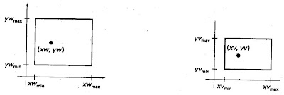
Firgure (a)
Figure (b) A point at position (xm, yw) in a designated window is mapped to viewport coordinates (xv, yv) so that relative positions in the two areas are the same.
Solving these expressions for the viewport position (xv, yv), we have
xv = xvmin + (xw – xwmin)sx
yv = yvmin + (yw - ywmin)sy
where the scaling factors are
Equations can also be derived with a set of transformtions that converts the window area into the viewport area. This conversion is performed with the following sequence of transformations:
1. Perform a scaling transformation using a fixed-point position of (xwmin, ywmin) that scales the window area to the size of the viewport.
2. Translate the scaled window area to the position of the viewport.
Relative proportions of objects are maintained if the scaling factors are the me (sx = sy). Otherwise, world objects will .be stretched or contracted in either e x or y direction when displayed on the output device.
Character strings can be handled in two ways when they are mapped to a viewport. The simplest mapping maintains a constant character size, even though the viewport area may be enlarged or reduced relative to the window. This method would be employed when text is formed with standard character fonts that cannot be changed. In systems that allow .for changes in character size, string definitions can be windowed the same as other primitives. For characters formed with line segments, the mapping to the viewport can be carried out as a sequence of line transformations.
From normalized coordinates, object descriptions are mapped to the viewport display devices. Any number of output devices can be open in a particular application, and another window-to-viewport transformation can be performed for each open output device. This mapping, called the workstation transformation, is accomplished by selecting a window area in normalized space and a viewport area in the coordinates of the display device. With the workstation transformation, we gain some additional control over the positioning of parts of a scene on individual output devices. As illustrated in Fig. (b), we can use work station transformations to partition a view so that different parts of normalized space can be displayed on different output devices.
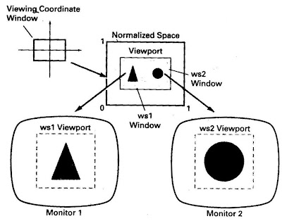
Figure (b)
Figure (b) Mapping selected parts of a scene in normalized coordinated to different video monitors with workstation transformations.
Exterior Clipping
So far, we have considered only procedures for clipping a picture to the interior of a region by eliminating everything outside the clipping region. What is saved by these procedures is inside the region. In some cases, we want to do the reverse, that is, we want to clip a picture to the exterior of a specified region. The picture parts to be saved are those that are outside the region. This is referred to as exterior clipping.
A typical example of the application of exterior clipping is in multiple-window systems. To correctly display the screen windows, we often need to apply both internal and external clipping. Figure 6-31 illustrates a multiple-window display. Objects within a window are clipped to the interior of that window. When other higher-priority windows overlap these objects, the objects are also clipped to the exterior of the overlapping windows.
Exterior clipping is used also in other applications that require overlapping pictures. Examples here include the design of page layouts in advertising or publishing applications or for adding labels or design patterns to a picture. The technique can also be used for combining graphs, maps, or schematics. For these applications, we can use exterior clipping to provide a space for an insert into a larger picture.
Procedures for clipping objects to the interior of concave polygon windows can also make use of external clipping. A line P,P, that is to be clipped to the interior of a concave window with vertices V1V2V3V4V5. Line P, P2 can be clipped in two passes: (1) First, P]P1 is clipped to the interior of the convex polygon ViV,V3V, o yield the clipped segment P'iP':) (2) Then an external clip of P'iP'z is performed against the convex polygon V,V,V, to yield the final clipped line segment P'i'2.

Figure (c): A multiple-window screen display showing examples of both interior and exterior clipping.

Like it on Facebook, Tweet it or share this article on other bookmarking websites.