What are Turbochargers? Complete Guide
To learn what are turbochargers, the first thing we must know is what is turbo power?

To carry out complete combustion of fuel oil, it is necessary to provide enough oxygen, which is not in majority in the air quantity. The more air we are able to introduce fuel into the cylinders of the engine, the more power that can be obtained, but the more mass of air necessary to burn, this necessity arises the idea of supercharged engines. The fresh charge enters the cylinder at a pressure much greater than the compressor inlet pressure and thus the inlet temperature will be equally high.
Overfeeding is to establish at the entrance to the engine's cylinders an atmosphere of air with a density higher than normal so that for a given volume of air, that air mass is greater, for it uses a number of accessories, which will differ depending on the type of supercharger used.
The supercharger or turbocharger is essentially a compressor driven by exhaust gas, whose primary mission is to press the intake air to thereby increase the amount that enters the engine cylinders in the intake stroke, allowing it to burn efficiently more amount of fuel. Thus, the torque and the final power can be increased up to 35%, thanks to the turbocharger.
This device has been designed to increase the overall efficiency of the engine. The energy to drive the turbocharger is extracted from the energy wasted in the engine exhaust gas is composed of a turbine wheel and shaft, a compressor wheel, a central housing which serves to hold the rotary joint, bearings, a turbine housing and compressor housing.
The turbine wheel is located in the turbine housing and is mounted on one end of the turbine shaft. The compressor wheel is located in the dcl compressor housing and is mounted at the opposite end of the axis of the turbine wheel to form a comprehensive set rotating.
The set consists of a rotating turbine wheel and shaft together forming a piston ring, a thrust spacer, wheel and compressor wheel-retaining nut. The rotary joint is supported by two bearings lubricated pressure maintained in the central housing by spring rings. Internal oil passages are drilled in the central housing to provide lubrication to the bearings of turbine wheel shaft, the thrust washer, thrust collar and thrust spacer.

The turbine housing is a casting of heat resistant alloy wheel that houses the turbine and provides an entrance flange of the engine exhaust gas and an outlet located axially exhaust gas turbocharger. The turbine housing is bolted to the turbine end of the central housing, thus providing a compact set and free of vibrations.
The compressor housing that houses the compressor wheel provides an ambient air inlet and a discharge outlet of compressed air. The compressor housing is attached by brackets to the end of central housing compressor.
According to the method used to achieve this higher density range (compressed air) can be distinguished:
Volumetric compressors: use some of the torque transmitted by the engine.

Turbochargers and Comprex system:
Both systems use the energy of the exhaust gases.
Volumetric compressors work directly coupled to the engine crankshaft, which transmits the rotation to some part of the volumetric compressor (depending on the type in question), which in turn introduces high-pressure air into the engine cylinders. The key advantage of turbochargers is that the compressor volumetric effects are seen even at low revs the engine. Its disadvantage is that steal some of the engine power to function but then returned with a vengeance. Some of the trademarks of compressors developed are:
Constitution of the turbocharger

The turbocharger consists of three sections: the central housing, the turbine and compressor.
The central housing contains two flat bearings, seals type segment and a separate sleeve. It also has pipes for the supply and discharge of oil into and out of the housing.
The turbine wheel rotates within the casing and is in solidarity with the central axis supported on a rotating journal bearings, coupled within the central housing. The compressor wheel, which is mounted at the other end of the shaft, a turbine with a set of simultaneous rotation.
A turbocharger can rotate at speeds of 120,000 RPM. In some high performance units.
Operation of the turbocharger
Generally speaking there are two types of turbocharger: the pulse and constant pressure. Each has its own operating characteristics, and yet both act the same basic shape.
The turbocharger is mounted on the exhaust outlet flange of the exhaust manifold of the engine. Once started the engine, engine exhaust gases passing through the turbine housing are rotating turbine wheel and shaft, the gases are discharged into the atmosphere after passing through the turbine housing.
The compressor wheel, which is mounted at the opposite end of the axis of the turbine wheel, rotates with the turbine wheel. The compressor wheel sucks in air compressor to housing environment, compresses air and sends it to the blower motor.
During operation, the turbocharger responds to engine load requirements reacting to the flow of engine exhaust gases. Cl with increasing engine performance increases the flow of exhaust gases and the speed and performance from a rotary increase proportionally to sending more air blower motor.
Some engines are equipped with inter coolers to reduce the discharge temperature of the turbocharger air before entering the blower
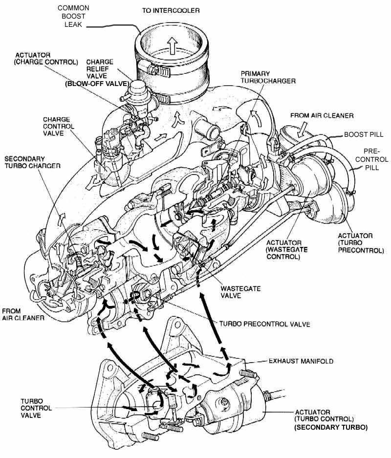
The type turbocharger boost, you need an exhaust manifold specially designed to carry high exhaust pulse energy to the turbine of the turbocharger. This design, with individual branches, as shown in Figure 4.4 avoids interference between the exhaust gas discharge from the various engine cylinders, thereby producing a stream of high-speed drive, which he achieves with other designs.
In some applications, the turbine casing is divided into two zones (momentum divided), thus securing better assistance to prime the whole rotation, the beginning thereof. The design has two chambers in a spiral, instead of one. The term "spiral chamber" is given by the spiral shape of the turbine casing hi, which decreases in volume toward the center, like a snail shell.
Each chamber receives half of the engine exhaust stream, eg a four-cylinder engine, the front two-exhaust gas is discharged into the camera first, while the other two do so in the second.
With the kind of constant pressure turbocharger, exhaust gas from all cylinders flows into a common manifold, where they disappear impulses, leading to a gas inlet into the turbine at a constant pressure.
In both types of turbocharger, exhaust gas entering the turbine spiral shape of a ring (torus), which produces a radial acceleration to a reduced pressure and increased speed on the turbine blades, which are specially designed, of so as to exploit the power of the gas to drive the turbine shaft and compressor wheel attached to it.
The overall compressor design and construction is similar in both the turbocharger boost, and the constant pressure.
The compressor consists of a wheel and a housing that is built into a single spiral or diffuser. Air enters the chamber of the compressor (suction at the turn of it) between the blades of the wheel and is driven by the effect of centrifugal force inside the coil during rotation of the wheel. At this time the air velocity decreases and produces a corresponding increase in pressure. As the air rises around the spiral, its speed is reduced and the pressure increases with the diameter of the cross section of the chamber.
In summary, the supercharger provides a quick impulse type excitation of the rotary joint, due to the rapid succession of pulses of exhaust gas on the whole turbine. It is primarily used in automotive applications, where it is important response acceleration.
The constant pressure turbochargers are mainly used in large diesel engines, bulldozers and marine applications where throttle response is not as critical.
Carburetor-fed engine, depending on where you put the supercharger system can distinguish two cases:
Placement of the turbocharger
Carburetor-fed engine, depending on where you put the supercharger system can distinguish two cases:
Carburetor Blower: The carburetor is located between the compressor and the intake manifold. Thus, the air entering the compressor is clean air directly from outside.
Aspirated carburetor: the carburetor is mounted above the compressor so in this case what is a compressed mixture of air and gasoline.
The latter system was most often used in the first applications of overfeeding, in its simplicity and because it provided an air-fuel mixture temperature lower than the blowing system.
However aculeate greatest use of blown carburetor system as this system allows the use of a heat exchanger or inter cooler. Diesel or gasoline engines fueled by injection this classification makes sense because the fuel injectors are always placed after the supercharging system
Intercooler system

The Intercooler system consists of a heat exchanger which introduces the air leaving the turbocharger to cool before feeding it into the engine cylinders.
On cooling the air reduces the density of it so for the same volume of the cylinder can introduce more air mass and thus improve engine performance.
Advantages Of Turbocharging

Since the turbocharger is activated by the energy of exhaust gas, which discharge to the outside is wasted, a turbocharged engine offers many advantages over the conventional type. Among them we can highlight:
Increased power to weight ratio
A turbocharger can increase power and torque of a diesel engine by 35% over the conventional version. Thus, turbocharged four or six cylinders, smaller, you can perform the work of another major, such as a conventional V8.
Reduced engine noise
The turbine casing acts as a set of noise absorption of the engine exhaust gases. Similarly, the compressor section inlet reduces noise produced by the pulses in the intake manifold. As a result, a turbocharged engine is usually quieter than other conventional, though generally perceived characteristic whistle when the engine is under load or accelerating.
Fuel Economy
A turbocharged engine has a higher volumetric efficiency than conventional, with which it achieves more complete combustion, which results in lower fuel consumption.
Smoke Reduction
The engine turbochargers supply the extra quantity of air in the operation at medium and high speed, resulting in a phase of combustion more efficient and clean, which reduces the production of smoke.
Disadvantages of Turbocharging
Reduced power at low revs
When it has only recently stepped on the gas and therefore a system of laps in, the exhaust gases are significantly reduced and this causes the turbo just work. The engine response is not very bright then unless you use a conveniently short way to increase the engine speed..
The maintenance of the turbo is more demanding than a naturally aspirated engine.
Turbo engines require a higher quality oil and oil changes more frequent, as it is subjected to harsher working conditions have to lubricate the bearings of the turbine and compressor often at very high temperatures.
Turbocharged engines require better materials and lubrication and cooling systems more efficient.
The turbo in the future
One of the most needed improvements in turbocharged engines has to do with his performance at low revs. Advances in this section leads to an improvement in the delivery of the turbine, together with increased flows and performance of the compressor.
To achieve this, one of the latest techniques used is the use of variable inlet turbines. This technique improves both the maximum values of torque and power as the answer to any regime.
Weight is another aspect to improve. In their latest models, Garrett (turbochargers manufacturer) has come to reduce weight by over 50% of the T3 model 7 kg to 3 kg of GT12.
The turbo petrol engine is another need increased reliability at high temperature. A full charge is good for 1000 ° C in the turbine and the most common material, called Inconel, undergoes changes in its structure from these grades. In the future austenitic stainless steel is used for surround, expensive today, but secured by its use in competition.
Compressor COMPREX
The Comprex type compressor uses energy transmitted by direct contact between the exhaust and intake by pressure waves generated depression in intake and exhaust processes. The results from Comprex quite large, and is driven by the crankshaft via a belt. For both reasons to choose placement opportunities are extremely limited.
- Gas chamber.
- Rotor.
- Transmission-belt crank-COMPREX.
- Manifold.
- A mixture of admission.
- A mixture of pressure.
- Engine exhaust gases
Comprex system, like turbo systems, harnesses the energy of the exhaust gases. Its main advantage is that it responds more quickly to changes in engine load, so it will behave more cheerful.
The main disadvantages of this system are:
- Rates two or three times higher than the equivalent of a turbocharger.
- Presence of a shrill whistle during acceleration.
- High temperature gas admission, having been in contact with the walls of the exhaust gases.
- Axial type turbochargers.
The axial turbochargers operate as fans of the same type, but typically are built in several stages. Each crown fixed blade diffuser plays the role of precedent for the rotor and distributor to the next. Its general constitution reminds us of the jet turbine.
The compression ratio per stage is significantly lower than that for a centrifugal compressor. With a circumferential speed of 200 to 250 m / s can be obtained, for air, a compression ratio of 1.08 per rotor, approximately.
The correction of the profile of the blades is of paramount importance, that profile should be considered in accordance with the laws of fluid mechanics. Indeed, the centrifugal force does not allow, as in the case of centrifugal compressors, the adhesion of the fluid with the wall of the blade, a small deviation of the inclination of the latter leads to the formation of eddies, the launch of the vein aureolic and desperado compressor. That is, the best performance corresponds to a varying flow margin very narrow, as on the other hand, the characteristic curve of pressure-flow has a steep, axial compressors are only suitable for applications where, for a speed constant, the flow is well determined.
However, certain axial compressors are equipped with a device for regulating the orientation of the blades, is turbocharged stationary, or with the running machine, which allows adaptation to the conditions of use.
The route taken by the fluid is much more straightforward than in the case of centrifugal compressors, which allows a building with smaller size and lower weight can be obtained in normal yield a significant increase optimum performance can reach the adiabatic 85%.
Axial compressors are used in the cycle gas turbines and turbojet aircraft, its employment. Its characteristic is the use of turbochargers refrigerated for large volumes (300 to 3000 m3/min.) And weak pressures (2 to 3 Kg/cm2 effective) for air injection in blast furnaces. Also, mixed compressors are built in the early stages which are of the remaining axial and centrifugal type.
Ideal cycles and processes
Although the combustion engine does not work according to a thermodynamic cycle cycle thinking is still a very useful file to show the effects of changes in operating conditions, to indicate the maximum performance and to compare one type of combustion engine with one over another.
When a hypothetical cycle assumes that the working fluid is air only, is called a cycle of normal air. It is considered that the heat is supplied directly to the cycle or rejected by him ignoring heat losses, while the calorific value of air is estimated to be constant.
Eaton Compressor Roots 1
This is a pure machine movement, which is not compressed air. The effective filling pressure is not created until the intake manifold.
This simple version with two rotor blades creates a relatively low pressure, and further creates very slowly with increasing engine speed.
The power input is located for an overpressure of 0.6 bar and maximum air passage, at 12.2 hp. Roots compressor performance is not very high and it gets worse with increasing engine speed. The supply capacity exceeds 50% only in a very limited range. Compressed air is extremely hot.
Eaton Compressor Roots 2
Like the previous compressed air either internally, however the excess load, under the same conditions, peaks higher.
The absorbed power is at only 8 hp and air temperature rises less. The performance of this compressor is over 50% in a higher range.
Volumetric rotary piston compressor Wankel: Its operation is similar to the roots, but vary substantially geometry. This will greatly improve the properties.
The pressure is reached is high. The power input for a pressure of 0.6 bar and maximum air flow reaches 8.2 hp. The air temperature does not rise much..
The yield is above 50% capacity and average circulation in a narrow range even exceeds 60%.
Propeller Sprintex Compressor
This compressor manufactured in Scotland has a high energy consumption for low supply capacity, the highest in nearly 11 hp. The cause seems to lie in the journal bearings of the compressor Sprintex aided by the internal friction rises too high air temperature. Performance is not very good, and only with high pressure and a high degree of air flow is about 50%.
Piston Rotary Compressor
This compressor has a kinematic relationship with the Wankel engine. A three-blade rotor describes a circular path in a rotating drum with four cameras. The cameras in their rotation they change their volume and thus the air is compressed within the compressor.
Energy consumption is very low also in part load, between 2.7 and 8.2 hp. The temperature rise is small. The performance of the compressor is over 50% in a wide range of average capacity of supply.
Piston Rotary Compressor KKK
It is a modification of the Roots compressor. The rotor turns a drum that surrounds it, it also rotates on its part. The creation of the load pressure and air flow is very fast in the KKK. The power required to achieve high pressure and high flow is relatively low, with values approaching the 8 hp. The air heats up very little overpressure. KKK compressor performance is very good and in a range around 50% and a range smaller than 60%.

G De Volkswagen Compressor
It differs from other models mainly because it is composed of elements in rotation to get the circulation. The compression of air in through the spiral follows an oscillating movement of the inner piece. The supply of the compressor characteristic G satisfies the requirement of rapidly building pressure. A high flow capability is coupled here with a low power consumption, as losses are very small friction in the bearings of the compressor G. The performance achieved in certain ranges of loading, maximum of 60%.
G Compressor Volkswagen is no longer used, and has been incorporated into some engines W. Polo, Golf and W. W Passat for less than a decade.

Like it on Facebook, Tweet it or share this article on other bookmarking websites.